I mentioned in my email order the other day that I found your website really helpful. While researching dynamos it popped up with loads great info and I was interested to read your opinions on what makes a good road light. Up until that point I was using a Magicshine SSC P7 on the front and a SMART Superflash on the rear, and I even had a Fenix L2P on my helmet set on strobe! I figured that would get me seen and I'd be safe... The more I read the more I came to realise that it might not be the best approach, and besides that I wanted the benefits of dynamo lighting and they didn't come with mega illumination and strobe settings. So, given your write ups of the Philips I decided to buy a SafeRide 60 and a Lumiring in July 2012. I wanted to share my experiences with the lights and show you the mod I've just made to increase the Lumiring LED power.
I liked the lights and although they didn't seem very bright to look at, other people seemed to like them. A chap flagged me down in his car to ask me what the Lumiring was, and another day a cyclist chased after me to ask the same question. This did surprise me but it gave me confidence that they were in fact very visible despite not being obviously bright. I began to understand that visibility is not the same as dazzlingly bright. I have the lights on my commuter / long distance bike which I use around 10 hours a week commuting on country lanes and in to town, and also for Audax events all the way through the night. They've been great and a real revelation.
Unfortunately I had them for three months before the standlight stopped working on my Lumiring. I couldn't figure out how to get in it so I put it in the X-ray machine at work (I work in electronics manufacturing) and sure enough I could see a broken capacitor rattling around.

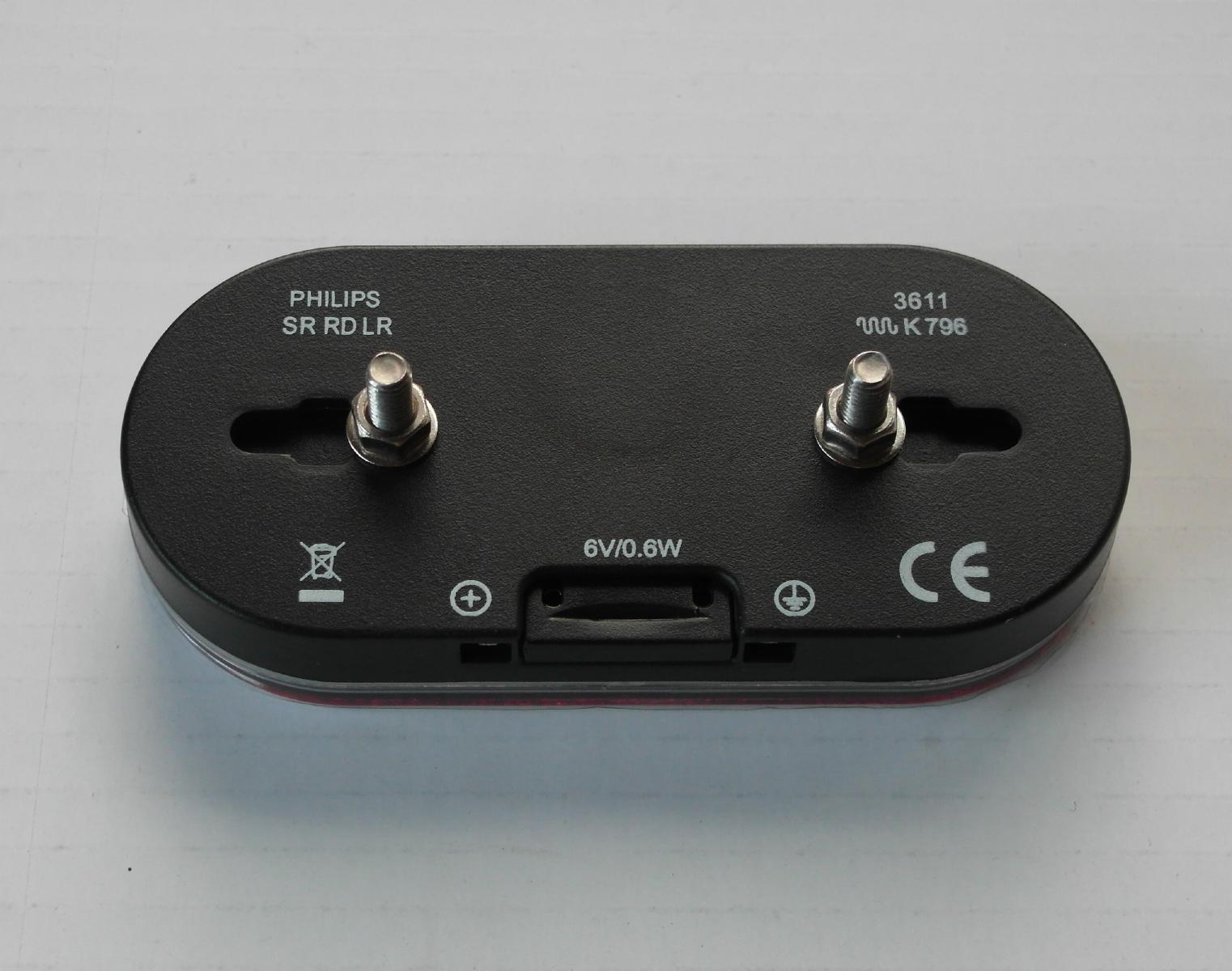
I called Philips customer care and had an amusing conversation with the call centre guy where I first had to convince him that Philips DO make lights, and then convince him that even though it was a dynamo light it was supposed to stay on when I stopped pedalling (he said it would need a REALLY big capacitor!). Once we'd got that out of the way he arranged for UPS to pick it up and take it away to be fixed. Shortly after I put the phone down he called back with a quick question: had I tried changing the batteries? I did laugh. Anyway, it went off with some X-rays and a note saying I thought the capacitor had snapped and that's why it didn't work. Two weeks later a brand new boxed light turned up with a letter apologising for the failure. Great service but I hoped the second one would last longer. It worked faultlessly for the next 10 Months until May 2013 when my friend lent his bike against mine and popped then lens right off. The lens is held with glue around the edge so it can be prised off and glued back on later. When mine came off it broke the spade terminal connections so it stopped working. At least I now know how it comes apart and I can have a good look and fix it. If you compare this one to the one I x-rayed you can see they are different. I wonder what they changed. You can see components and holes are in different places. These photos are taken after touching up the dry joints and before washing the flux residue off.
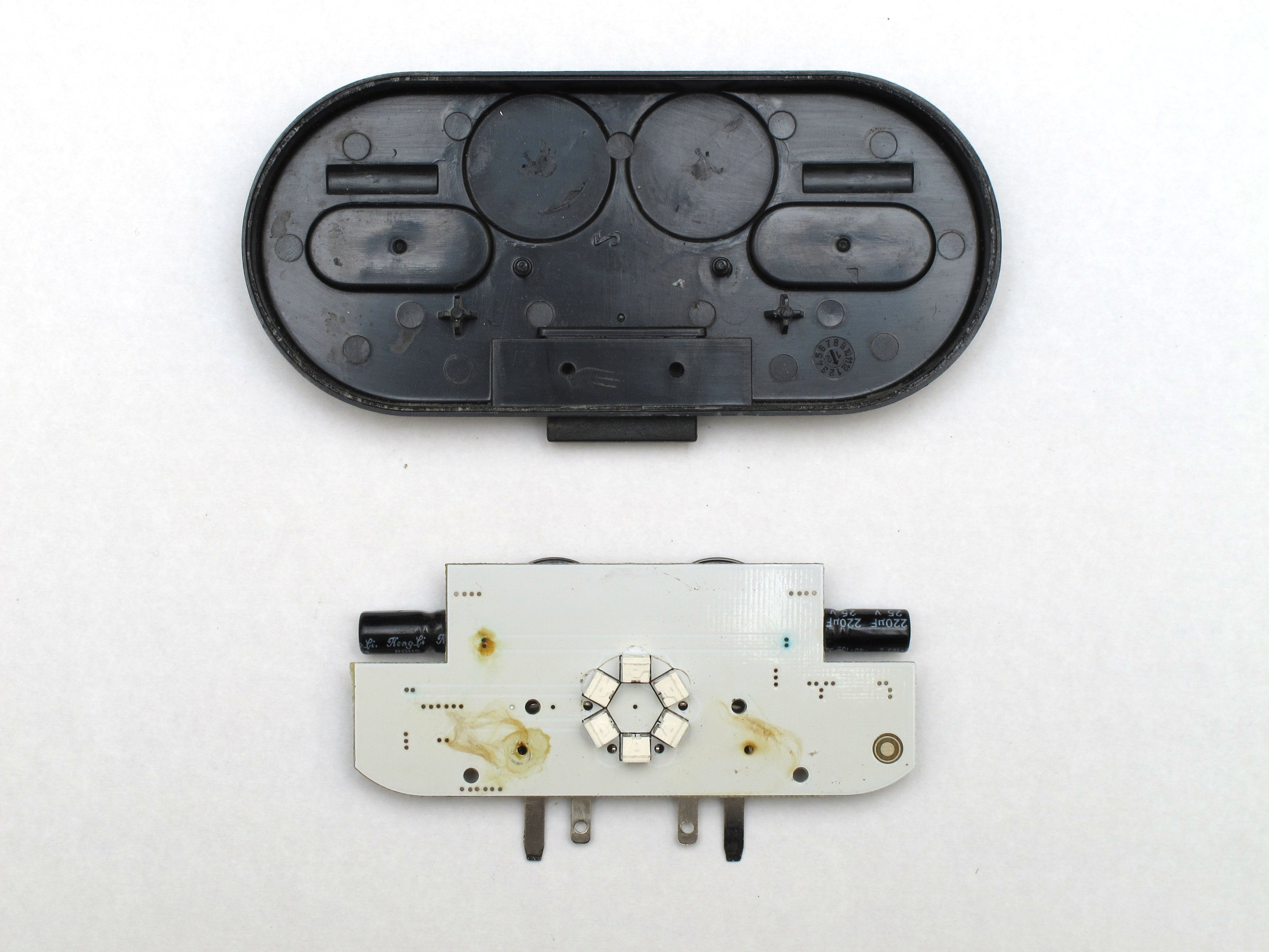
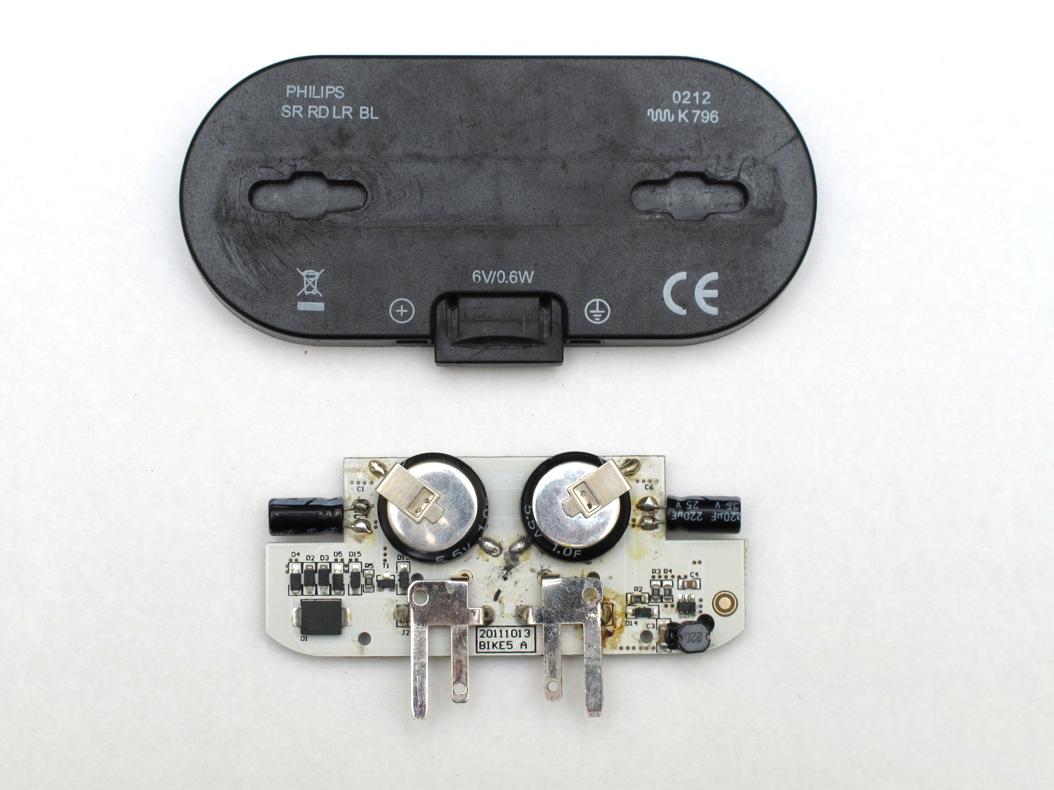
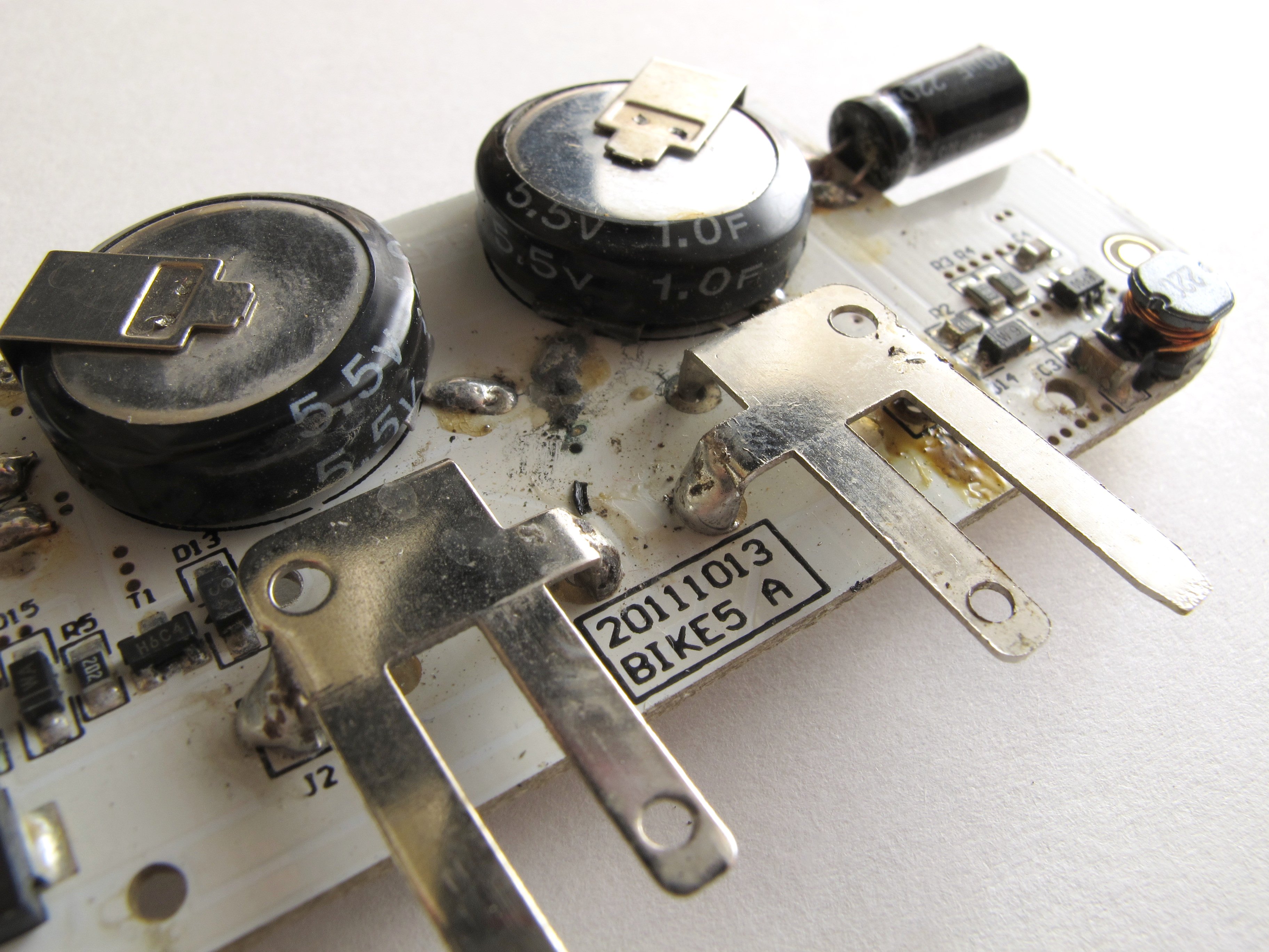
I was quite surprised to find that build quality is very poor particularly for a light to be used on a road vehicle. It doesn't even meet IPC Class 1 which is the lowest electronics manufacturing standard. At work we say Class 1 is only fit for singing santas, the kind of electronics that you don't expect to keep working until the end of Christmas! The spade terminals were barely soldered in with only a small amount of solder on the top side, and only two of the four pins are even soldered in! It's no wonder they came off when knocked. The capacitors were not fixed to the board either so there was a chance the connections would fracture a some point in the future due to the vibration. I un-soldered one side of each capacitor and put a double sided sticky pad under each one before soldering it back in and touching up the spade terminals. After that I took some photos, checked it all worked and then washed all the flux off in Isopropyl alcohol. I put a zip tie around the lens to hold it on and it's worked fine ever since. I never got round to gluing it because in the back of my mind I remember reading your comment about making the light brighter.
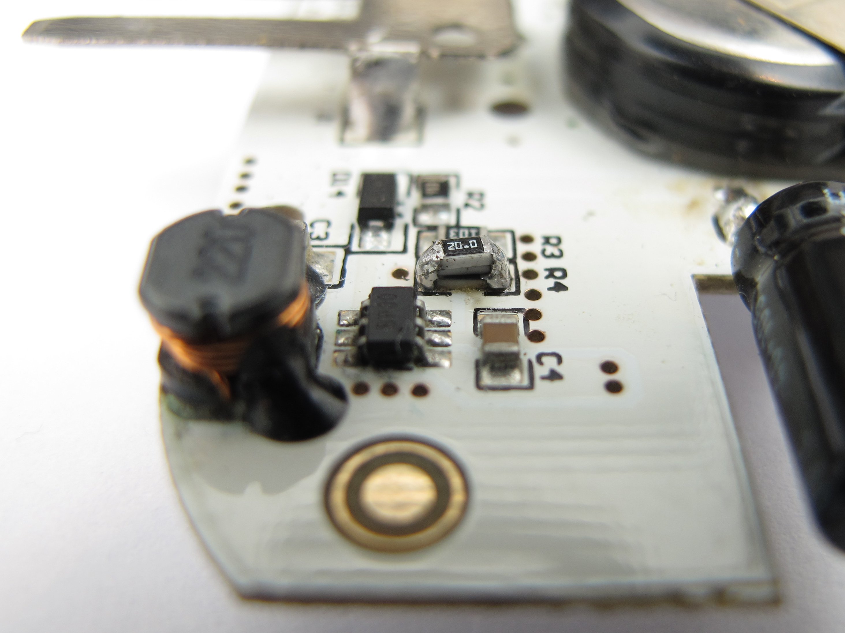
I was curious to see if I could tweak it to increase the output and I finally got round to it this evening. I traced the circuit and identified the LED driver chip used on the board, it's a Semtech SC4509, the little 6 pin device in the far right corner with the marking BP00 on top. I've attached a copy of the datasheet and in it you can see that the LED is set by the sense resistor in between pins 2 and 3. Philips are using an 18R which using the drive current formula from the datasheet gives 199/R = 199/18 = 11mA. The max drive current of the chip is 30mA so I figured I'd try bumping it up to that and see if it was too bright. All I had to do was change the resistor to 6.6R, an easy mod. I calculated that two 20R resistors in parallel with 18R would give 6.4R, so I soldered a couple on top and fired it up.
In my rather unscientific test it looks a lot brighter than it did before, quite a lot brighter, but still not annoying. How much brighter do you think this type of light can be before it's too bright and worse for it? Unfortunately I didn't take any photos of the output before the mod and haven't even tried it on my bike yet but I'll spend some time with it and let you know. I also wonder if the power consumption would be undesirable. I certainly like the fact the standard Lumiring is low power.
And before I go I also have some feedback on the Saferide 60 front light :-) I like the light although it sometimes seem lacking next to my friends B&M Cyo. I think that's because the Cyo has more of a focused beam. i haven't tried riding with it but I think I would prefer the even Philips, it's like you don't know it's on in a good way. My light has worked fine but I was always worried that the bracket was going to snap and it finally did in July 2013, one year after I bought it. I'm pretty certain it was because I purposefully bent it to fit out of the way of my new bag. It was fine up until then but less than a week after I bent it it snapped. I doesn't feel like it can take any manipulating. I soon brazed a new one out of some steel tube but it is a touch heavier!
(email 2, with additional information after my question of publishing the email + pictures on my site)
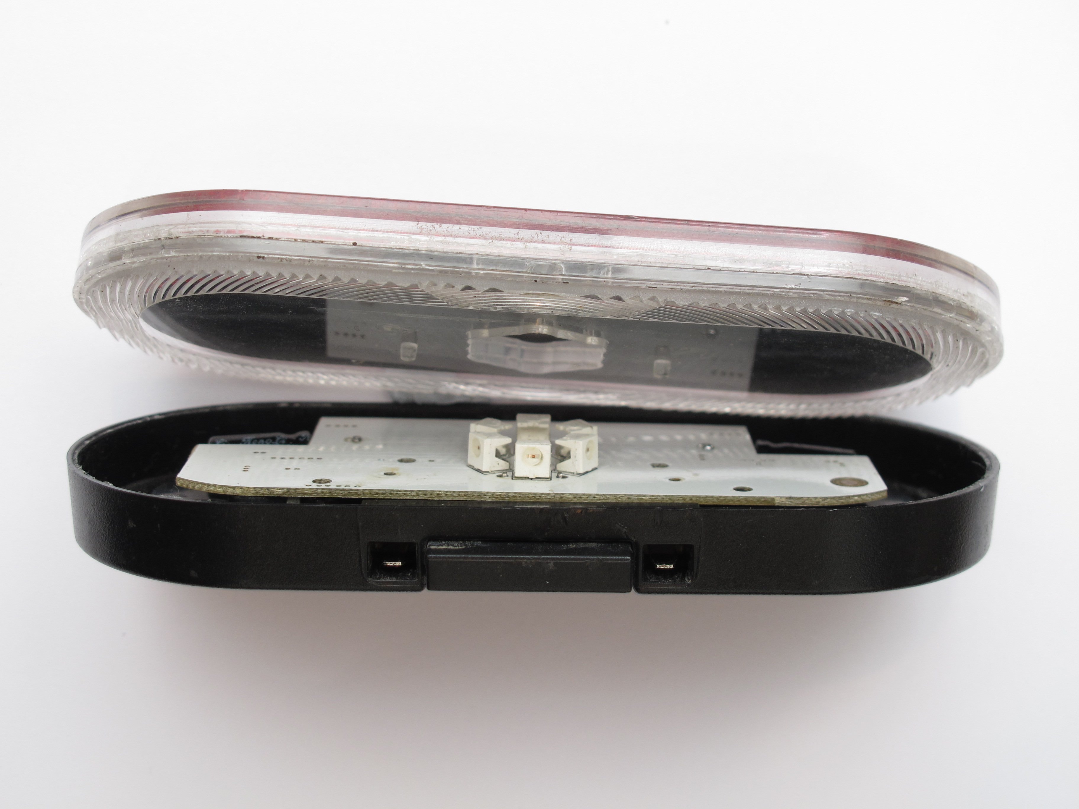
I realised I hadn't included a picture of the lens and how it fits on the case.
In the photo you can see the shoulder around the bottom edge of the lens and see how it will locate on the case. The lens is only glued on to the case so once you break the glue the lens will come away from the bottom easily. Make sure you pull the pieces apart and don't slide them. The LEDs sit up in a little hollow in the lens and they would be knocked off if you separated the pieces with a shearing motion. To take the PCB out of the case first pull the connector drawer out towards you and then lift the back edge of the PCB so you can see the coin shaped capacitors on the bottom side. You need to lift the PCB up high enough so that those capacitors can clear the back edge of the case then wiggle the board away from you. The terminals and the downward force of the lens are the only things holding the PCB in the case. Some plastic fusion glue should do a good job of sticking it back together.
I haven't measured the current drawn by the light but I should point out that it will increase more than the LED current, just because the LED driver circuit is increasing the voltage across the string of LEDs, so 30mA through the LEDs equates to 50mA at the dynamo.
Measured LED Forward Voltage = 1.7V
Total LED String Voltage = 6*1.7V = 10.2V
LED Power at 30mA LED current = V*I = 10.2 x 0.03 = 0.3W
Current at 6V = P/V = 0.3/6 = 50mA
And this doesn't include any of the other losses so I should just measure it!
I'm afraid I don't have the date of manufacture for the first light I had but it definitely looks like a different circuit from the X-ray.
My standlight will now last 1/3 of the time since I've tripled the LED power. I'll have to see how that works out.
Phil